


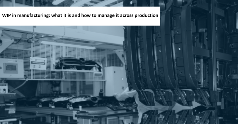
A plastic bumper fascia leaves an injection molding machine. The part has already taken shape, but its manufacturing process is not yet complete. Depending on the plant’s production process, it may still undergo inspection, surface preparation, painting, component assembly and sequencing before being sent to the vehicle assembly line.
Throughout this journey, the part accumulates production costs, uses system capacity, moves through the plant and, at certain points, waits. It is no longer raw material, but it is not yet a finished product either. It is WIP.
The term often appears in financial reports, production metrics and Lean manufacturing. On the factory floor, however, WIP also has a physical reality: it consists of parts that must leave one operation, reach the next and retain their identity, status and, when required, sequence throughout the journey.
Understanding WIP means considering both dimensions. On the one hand, how much work and value remain within the production process. On the other, what is actually happening to the parts as they move between operations.
What is WIP in manufacturing?
WIP stands for Work in Process. In manufacturing, it refers to materials, components and products that have entered the production process but still have one or more operations to complete. It is also known as work-in-process inventory or in-process inventory.
WIP does not include only the parts currently inside a machine. It can also include parts in internal transport, waiting for the next operation, pending inspection, on hold for quality reasons or set aside for rework. What defines its status is its stage in the manufacturing process, not whether it is moving or waiting.
Within the production cycle, WIP occupies an intermediate position:
| Inventory category | Status within the process |
|---|---|
| Raw materials and components | Have not yet entered the stage of production being analyzed |
| WIP or work in process | Have entered production but still have operations to complete |
| Finished goods | Have completed the defined operations and are available for shipment, integration into another process or final use |
The boundary depends on the scope being analyzed. A subassembly may be considered a finished product by the supplier that manufactures it and then become a component when it reaches the customer’s plant. Even within the same factory, WIP can be measured within a single production line or across a flow linking several production areas.
Defining this scope is essential. If WIP is counted across injection molding, painting and assembly but compared with the output of only one of those areas, the calculation will not be internally consistent.
Work in Process or Work in Progress?
Work in Process and Work in Progress share the acronym WIP and are often used interchangeably. The difference lies mainly in the context in which they are used.
In manufacturing, Work in Process typically refers to materials, parts or physical products moving through a sequence of operations. Work in Progress has a broader meaning and can also apply to projects, services or tasks that have not yet been completed.
The distinction is not universal, and some organizations use both terms interchangeably. Throughout this article, we primarily use Work in Process because our focus is on the flow of physical parts between manufacturing processes.
How is WIP calculated?
WIP can be expressed either as a monetary value or as the physical amount of work within a process. The accounting calculation determines the value of the inventory, while the operational calculation relates the units in process to throughput and flow time.
The accounting value of WIP
From an accounting perspective, WIP represents the production costs assigned to units that have entered the manufacturing process but have not yet completed it.
Depending on the costing method used, WIP may include:
- Raw materials and other materials consumed.
- Labor directly related to production.
- Other costs directly attributable to the product.
- An allocation of manufacturing overhead.
Conversion costs typically include costs directly related to production and a systematic allocation of fixed and variable production overheads. The exact composition depends on the applicable accounting framework and the costing method used by each organization.
A bumper fascia that has already been painted may have accumulated more production costs than one that has just left injection molding, although how this progress is reflected will depend on the company’s costing system.
In simplified terms, the movement in the WIP balance during an accounting period can be expressed as follows:
Ending WIP = Beginning WIP + Production costs added to WIP − Cost of units transferred out of WIP
The production costs added to WIP include both the costs incurred on units that were already in process and those associated with new units started during the period. When a unit completes the process being measured, its accumulated cost is transferred out of WIP and into the next production stage or inventory category.
WIP, throughput and flow time
From an operational perspective, Little’s Law relates average WIP, average throughput and average flow time within a stable system. Throughput is the rate at which the system completes units.
Average WIP = Average throughput × Average flow time
If a production line completes an average of 20 units per hour and each unit spends 3 hours within the process:
20 units/hour × 3 hours = 60 units of average WIP
Flow time includes processing operations, internal transport and waiting within the scope being analyzed. It is not the same as the time during which the part is actually being processed.
This relationship helps interpret an increase in inventory. When comparing two stable operating conditions, if throughput remains at 20 units per hour while average WIP rises from 60 to 100 units, average flow time increases from 3 to 5 hours. There is more work within the system, but its output rate has not increased.
This calculation requires representative averages and a consistent system boundary. WIP across an entire plant should not be compared with the output of a single workstation, and a temporary buildup should not be treated as a new steady state. Little’s Law also does not identify the cause of an increase in WIP. That requires closer observation of the production process.
What can WIP reveal in a manufacturing plant?
Formulas make it possible to quantify WIP, but they do not explain by themselves what is happening in the plant. To interpret it, it is necessary to observe where it accumulates, how long it remains there and why it is not progressing.
| What is observed | What should be investigated |
|---|---|
| Parts repeatedly accumulate before an operation | Capacity, stoppages or cycle times in the downstream process |
| Some units remain stationary longer than expected | Quality issues, lack of an assigned destination, transport problems or process blockages |
| A process runs out of material even though there is WIP in the plant | Part locations, supply routes and delivery sequence |
| Parts need to be located, repositioned or reordered manually | Identification, traceability and the design of the flow between operations |
| The digital record does not match the parts physically present | Unconfirmed movements, identification errors or material outside its intended route |
These signs indicate where to begin investigating, but they do not determine the root cause by themselves. If a workstation cannot unload, the immediate source of the blockage is downstream. If it is waiting for material, the problem lies upstream or in the transport system connecting the two operations.
For this reason, it is not enough to state that there is “too much” or “too little” WIP. Its distribution, how long it remains and its status also matter. The useful question is not only how much work is within the system, but where it is, why it remains there and what it needs to continue.
Many of these signs appear precisely in the connection between operations, where WIP moves, waits or changes route.
What happens to WIP between two processes?
Between two processes, WIP must travel a certain distance and adapt to the way the next operation works. Intralogistics connects production rates, batches and sequences that do not always coincide.
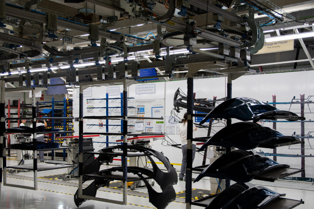
Injection molding may produce one part variant for an extended period, while the paint shop organizes its incoming flow according to a different mix of parts. Further downstream, assembly may require them in a different order. More than a transport route is needed between these areas: the supply must be prepared in the form that each operation can receive.
Conveyor speed is only one part of the answer. If the destination cannot receive material, moving it faster only makes it reach the queue sooner. If a specific part variant is required, delivering any available part is not enough either.
The design of the flow between processes must determine where parts wait and the criteria under which they continue: in order of arrival, by batch, for replenishment or according to a production sequence. It must also account for exceptions. A part sent for rework requires an exit route and a reintegration rule that do not force the entire supply flow to be manually reordered.
When does a WIP buffer protect the flow?
A WIP buffer is an accumulation capacity designed to temporarily decouple two parts of the process. It protects the flow when it addresses a specific need, has a calculated capacity and follows a clear entry and exit rule.
Suppose the paint shop stops for ten minutes. If injection molding and painting are fully coupled, the interruption can immediately propagate upstream. An intermediate buffer allows parts to continue leaving injection molding for a period of time and wait in an orderly manner until the paint shop can receive them again.
The same buffer can provide protection in the opposite direction. If injection molding stops, the accumulated units can keep the paint shop supplied for a few minutes and prevent the process from running out of material.
This protection does not depend only on the total number of positions. It also depends on the occupancy level when the interruption occurs. A completely full buffer can supply the downstream process, but it has no space to continue receiving parts. An empty buffer provides receiving capacity, but it does not protect the downstream process against a lack of supply.
How to manage WIP intralogistics
Physically managing WIP requires the material handling system to execute the production rules. The layout and control logic must define capacities, routes, waiting points, priorities, sequences and exception handling.
It is not enough for a part’s destination to exist in the IT system. The material handling system must execute the movement, confirm that it has taken place and keep the unit accessible until it can be released. An installation with sufficient theoretical capacity can perform poorly if one part variant blocks the others or if every stoppage requires the sequence to be rebuilt manually.
WIP on an overhead conveyor
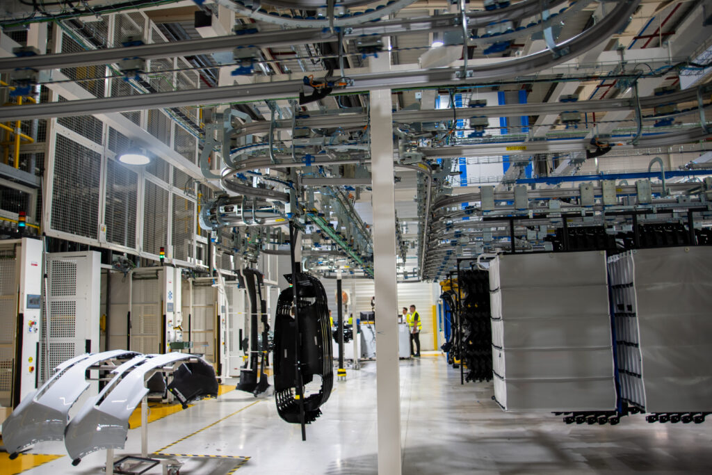
An overhead conveyor can combine transport and accumulation within the same installation. Depending on its configuration, it may also incorporate switches, changes in elevation and waiting areas, making use of the available overhead space when the layout allows.
For parts with sensitive surfaces, the hook makes it possible to define the contact points and reduce certain intermediate handling operations. Its geometry determines how the part is presented to the operator or robot and how much space it occupies while moving, turning or accumulating. For this reason, capacity is not calculated solely from the available meters of track.
The solution can be manual or automated. The choice depends on throughput, distances, the variety of part variants and the loading and unloading method. A manual installation can also incorporate identification and guidance systems that indicate where each hook should be placed or collected. Controlling WIP does not require automating all its movements.
In Power & Free systems such as Esyconveyor, the trolleys that move the hooks can stop in designated areas while others continue along their route. This facilitates accumulation and selective release, but it does not make every part of the installation independent. If several areas share a drive or transfer point, a stoppage can affect more than one route.
The distribution of drives and transfer points therefore determines how far the flow can continue when one part of the installation stops accepting parts.
Coordinating supply, return and recirculation
Managing WIP intralogistics involves coordinating all the movements that keep the supply between processes active. In a hanging-part installation, loaded hooks carry parts to the next operation, while empty hooks return to the loading points to be reused.
This circuit keeps the required hooks available, makes use of them throughout their operating cycle and reduces manual movements between areas. The return of empty hooks is therefore not a secondary route, but part of the flow that supports production.
When the installation handles multiple part variants, recirculation also provides flexibility. If the required hook is not in the first position on an accumulation bar, the hooks ahead of it can temporarily leave and then re-enter through a predefined route. This provides access to the required part variant without manually removing or repositioning the hooks.
By integrating supply, return and recirculation into the same design, intralogistics can adapt to different part variants, batches and production requirements while maintaining an organized and continuous flow.
Traceability and software for WIP
WIP control does not end with physical movement. To direct each part, the identity of the trolley or hook must be linked to production information such as the part reference, production order, quality status, next operation and destination.
In an automated installation, the MES can provide information about orders, part references and production requirements. The intralogistics software uses this data to apply routing, storage, priority and release rules.
The exact architecture depends on each plant. What matters is that the recorded status matches the physical reality and that every movement updates the available information. Traceability must also account for exceptions such as failed readings, parts removed manually, empty hooks or parts reintroduced after rework.
In the FORVIA Wałbrzych case, the project includes PLC-level control and communication with the robotic cells and the plant MES. This connection makes it possible to coordinate reference-based storage, paint line feeding and the subsequent reorganization of the flow while maintaining FIFO.
Software does not replace well-designed physical logic. It connects that logic with production information so that the physical movement of WIP and its digital status progress together.
Turning WIP into a controlled flow
A significant part of a factory’s actual performance is determined between one operation and the next. This is where parts can lose their sequence, occupy production floor space, require additional handling or stop the process. But it is also where well-designed intralogistics can provide continuity, flexibility and control.
At Esypro, we work precisely in this space. We design overhead transport and storage systems that connect processes and make it possible to move, elevate, accumulate, distribute and sequence parts within a single solution.
We do not start with a standard conveyor, but with the flow that each plant needs to achieve: the required throughput, the available routes, the accumulation capacity, the part references to be managed and the way production must recover after a stoppage.
Managing WIP is not simply a matter of moving parts from one point to another. It means creating a system in which each part can move forward, wait and resume its route according to actual production requirements.
Let’s design the flow your plant needs
We design overhead conveyors and storage systems to move, accumulate and sequence parts between processes, tailored to your layout and production rate.
Frequently asked questions about WIP in manufacturing
Yes. If it has entered the manufacturing process and still has operations to complete, it remains WIP. It may be inside a machine, in transit, accumulated, on hold for quality reasons or awaiting rework.
It can be measured in both ways, but each answers a different question. In operations, WIP is usually expressed in parts, batches or orders to determine how much work remains within the process. From an accounting perspective, it is expressed in monetary units to value the costs incorporated into products that have not yet completed manufacturing. The two measures complement each other: the number of parts does not indicate their monetary value by itself, while the accounting valuation does not show how many units there are, where they are located or how long they take to progress.
Not necessarily. Some WIP may protect the process against small variations. It becomes a warning sign when it grows persistently, remains stationary or accumulates at one point without improving throughput.
There is no single amount that is valid for every plant. It depends on cycle times, throughput, stoppages, batches, the mix of part references and recovery capacity. The objective is to protect continuity without creating permanent accumulation.
Intralogistics organizes how parts are transported, accumulated, identified and sequenced between operations. An appropriate system keeps WIP within known routes, capacities and rules, although it cannot correct imbalances in the production process by itself.