


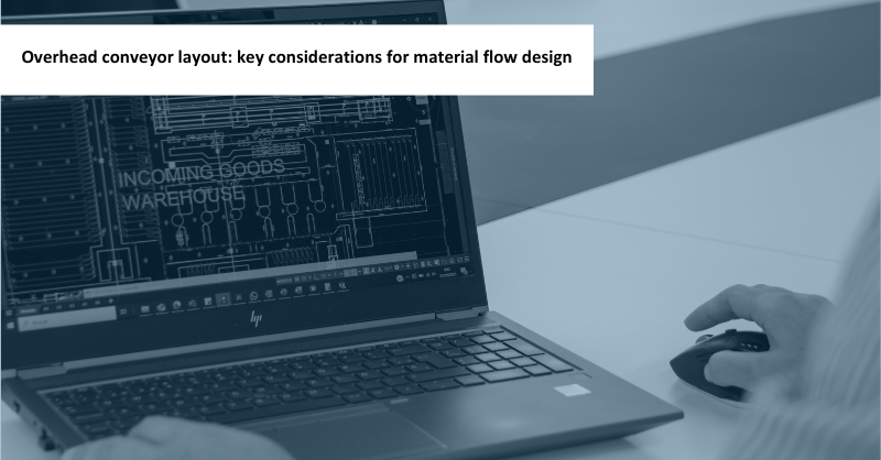
When evaluating an overhead conveyor for your plant, the layout helps you visualise how processes will connect and how the available space will be used. But what should you look at to determine whether the proposed solution can keep pace with production?
An overhead conveyor layout defines the arrangement of tracks, loading and unloading stations, accumulation zones and, where applicable, connections between levels. These decisions influence how many parts can move through the system, where they wait and how they reach each station.
A storage system can hold stock while a production line is still waiting for parts. That is why, when reviewing a proposal, the ability to deliver the required part numbers at the right time matters just as much as storage capacity.
In this article, we explore the key considerations when evaluating the layout of an overhead transport and storage system: part characteristics, throughput, empty hooks returns, buffers, safety and scope for future changes. These points will help you assess a proposal and understand how well it meets your plant’s actual needs.
What processes should the overhead conveyor connect?
The plant floor plan shows the available space. Defining the flow also requires an understanding of what happens in the processes being connected.
Consider several injection moulding machines feeding a paint line. Each machine may handle different part numbers, batch sizes and production rates, while the paint line follows its own schedule. The system must manage these differences and keep the parts needed by the next process available.
That is why a proposal should start with specific questions: where parts are produced, where they are used, which stations operate simultaneously and what happens during a changeover from one part number to another.
How the areas are connected also matters:
- In a closed flow, units remain within a track network connecting the stations and storage areas.
- In an open flow, part of the journey between areas is covered, for example, by transport carts. Loading, moving and unloading these carts must be factored into the overall flow time.
Both configurations can make sense, depending on the plant. The proposal must account for the entire route, including transfer points, waiting times and the return of empty hooks.
Parts shape the layout from the outset
A part’s dimensions and weight are essential inputs, but they are not enough to determine how it should be transported. Its finish, how it is secured, its orientation and the access needed for loading and unloading also play a role.
A part may appear compact when viewed from the front yet require considerable clearance when turning. A hook that carries several parts can reduce the number of movements but require more accumulation space.
The clearance envelope, the space needed for the complete assembly to pass through, must account for the trolley, hook and parts throughout their journey. This check affects curves, track spacing and connections to stations.
In manual operations, the height and orientation of the part affect how it can be handled. Where a robot is involved, the part’s position must be compatible with the operation it performs.
When evaluating the layout, it is worth checking which parts and hook configurations have been used as the basis for the design. If these are still estimates, identify what will need to be confirmed before finalising the solution.
Safety and access: space the layout must also allow for
The space required for an overhead conveyor includes areas where people can work, move around and carry out maintenance safely. These needs should be considered from the earliest proposals, as they can influence routes and equipment positioning.
Depending on the risks associated with each installation, safety fencing, guards, controlled access or other protective measures may be needed. Lifts, transfer points and loading and unloading stations require particular attention, especially where people can reach moving components.
When reviewing the layout, check that it provides for:
- Clearances and safety distances between moving loads, equipment and accessible areas.
- Space for protective measures and their access points, including room for doors to open where applicable.
- Aisles and evacuation routes that are compatible with the plant layout.
- Access for cleaning, inspection and maintenance, taking into account how these tasks will be performed.
The specific measures must be defined through a risk assessment and the requirements applicable to the installation. Incorporating them at the design stage helps establish the actual space the solution needs and anticipate changes that could affect its capacity or operation.
Can the overhead conveyor keep pace with production?
Transport capacity must meet demand at the stations under the conditions in which they operate. An overall figure in parts per hour needs context: which part numbers are being moved, how many parts each hook carries and how many stations need parts simultaneously.
A hypothetical example illustrates the difference. Supplying 240 parts per hour with four parts per hook requires 60 loaded hooks per hour. If the average load drops to three parts, 80 are needed.
Production still needs the same number of parts, but supplying them requires one-third more loaded hooks to pass through the system.
When reviewing a proposal, check whether the planned throughput accounts for partially loaded hooks, different hook capacities and changes in the mix of part numbers. Also consider what happens when several stations request material at the same time.
What matters is understanding the throughput the system can sustain under the expected operating conditions, as well as its capacity in an ideal scenario.
Empty hooks are part of the flow too
After the parts have been unloaded, the hook needs to return to a loading point or wait until it is used again. If empty hooks do not reach the right station, loading can stop even when parts are ready.
Let’s return to the example of 60 loaded hooks per hour. If each hook passes through the same section once when loaded and once on its empty return, that section handles 120 passes per hour. This simplified scenario shows why the number of parts delivered does not tell the whole story of internal traffic.
There may also be movements to inspection or maintenance areas and recirculation: units travelling through the system again to allow another unit to be retrieved or to reach a suitable location.
Mapping these flows on the layout helps identify where they share tracks and where they may interfere with one another. This provides a basis for assessing separate routes, waiting areas and movement priorities.
Bottlenecks in an overhead conveyor: what to check
In an overhead conveyor, some points handle more movements than others. Merges onto a shared track, storage entry and exit points, and lifts can affect the throughput of the entire system.
A merge point is where several routes join the same track. Here, flows must take turns passing through. If one has to wait, it can delay the units behind it.
The same applies to lifts. Their capacity depends on how much they carry per trip and on the complete cycle: receiving the load, travelling, unloading and becoming available for the next operation. If the exit is occupied, the lift will have to wait.
The proposal should account for these interactions, particularly when connecting several stations, moving between levels or combining inbound, outbound and return movements.
A compact layout can make good use of space, but it must also allow flows to share that space without blocking one another. When comparing alternatives, it is worth understanding where movements are concentrated and how capacity at those points has been checked.
Buffers: maintaining supply as processes vary
A buffer is a temporary accumulation area that helps absorb differences between supply and consumption. It may hold parts waiting for the next process or empty hooks ready for loading.
Its purpose is straightforward: while the next replenishment is on its way, the station has units available to keep working.
The required buffer coverage depends on the consumption rate and replenishment time, including any relevant waits and transfers. A station located far from storage or supplied through several pieces of equipment may need different coverage from one supplied directly.
When reviewing the layout, ask what variations each buffer needs to absorb and how long it can cover the expected consumption.
Location matters too. An accumulation area must allow units to wait without obstructing other routes. If it blocks a shared track when full, delays can spread to other stations.
A buffer can only cover temporary differences. If consumption consistently exceeds supply capacity, the reserve will eventually run out. That situation calls for a review of the flow’s capacity.
Storage capacity: how much can be stored and how much can be supplied?
Two proposals with the same number of storage positions can perform differently.
Physical capacity indicates how many units can fit. Operational capacity considers how many can be managed while maintaining the planned movements and supply rates.
In a hanging-part storage system, this depends on the variety of part numbers, hook types, partially loaded hooks and the space needed to manage empty hooks and internal movements.
For example, if several part numbers share a storage rail and a required hook is behind others, the units ahead of it may need to recirculate so it can be retrieved. This operation takes time and uses transport capacity.
An overall storage figure should therefore come with an explanation of how much stock of each part number can be held and at what rate it can be supplied.
Batches, replenishment or sequencing: how each station needs to receive parts
The supply method influences both the system layout and how it is managed. Moving the right quantity is part of the objective; it must also be delivered in the way the process requires.
| Supply method | Process requirement | What the solution must account for |
|---|---|---|
| Batch supply | Receive a specified quantity before switching to another part number. | Space to prepare and transfer the batch. |
| Replenishment | Replace units as they are consumed. | Buffer coverage during the replenishment time. |
| Sequenced supply | Receive units in a defined order. | Areas to build and maintain that sequence. |
The FIFO principle means that the first units in are the first units out, within the area or process where it applies. An assembly line may require a different sequence, so these two requirements must be distinguished.
To deliver parts in sequence, the system needs to know demand far enough in advance to locate, arrange and supply the units. This makes the available information and when it arrives part of the project definition.
It is worth establishing from the outset what each station needs and how that requirement will be communicated to the system.
Starts and stops: how the system responds
A system must handle situations beyond steady production: the start of a shift, a stoppage, a changeover to another part number or a change in consumption.
For example, keeping a buffer supplied during production does not guarantee that it will be ready for the first deliveries of the day. And a layout that works with a particular mix of part numbers may behave differently when demand changes.
The assessment of the proposed solution should identify the scenarios relevant to the plant and check how they affect supply.
There is no need to anticipate every imaginable situation. However, it is worth agreeing on the operating conditions the proposal must cover, so that the customer and supplier assess the system on the same basis.
What changes can the overhead conveyor accommodate?
Over the lifetime of a system, parts, production volumes and station assignments may change. Flexibility depends on the decisions made during the initial design.
An area designed for a single hook geometry may require mechanical modifications if it is used for a different part. Similarly, changing an assignment in the software will only be enough if the route and destination are physically compatible.
Before finalising the layout, it is useful to review:
- Which part numbers can share stations or storage areas.
- How much scope there is to accommodate increased demand.
- Where and how the system could be expanded.
- Which changes would require modifications to hooks, tracks or equipment.
A flexible proposal should explain what can change and under what conditions. This information helps assess the solution beyond the needs of day one.
From layout to day-to-day operation
Designing an overhead conveyor means bringing together many decisions: which parts to move, how much to store, how to supply each station and how much room to allow for change. A good layout ensures that everything works together when the plant is running, too.
That is why working with a partner specialising in overhead conveyors and hanging-part storage adds value from the earliest stages: it helps you ask the right questions, anticipate challenges and choose a solution that meets your actual operating needs.
At Esypro, we work with you to turn those needs into a transport and storage solution. Tell us what you need to connect. Let’s start there.
Considering a new overhead conveyor?
We design your system around your parts, your space and your production goals.
Frequently asked questions about overhead conveyor layouts
Designing an overhead conveyor layout requires a plan of the area, available heights, part characteristics, loading and unloading points, and required throughput rates. If the system includes storage, quantities for each part number and the supply method must also be defined: batch supply, replenishment or sequenced supply.
The layout determines which routes units share, where they can wait and how stations and equipment are connected. Merge points, lifts and accumulation zones can limit supply if they are not sized to handle the planned movements, including empty hook returns.
No. Accumulation and sequencing depend on the overhead conveyor’s technology and configuration. Some solutions are designed to transport parts, while others also allow them to accumulate between processes. Delivering parts in a specific sequence also requires routes, waiting areas and system management designed to maintain the required order.
When comparing two overhead conveyor proposals, check that both are based on the same parts, throughput requirements, storage needs and operating conditions. Alongside price and footprint, assess the effective supply capacity, empty hook returns, access for operation and maintenance, and scope for expansion.